Configuring Blender
Now that you've installed Blender, let's set it up ready for some work.
This section is especially important for laptop users or people who prefer to use a mouse with their left hand.
Discovering Blender's hidden menu-
Blender has a hidden menu, and it's here where the bulk of configuration relating to Blender is done.
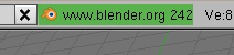
To access the hidden menu, place your mouse cursor over the border between a 3D view-port and Blender top menu bar.
The cursor will turn into a 'double-headed' arrow.
When you see this, LMB click, and drag downward.
The hidden menu will appear.
The image below shows the border under which the hidden menu can be found.
 For the most part you can leave the settings you find in the hidden menu as they are.
There are a couple you might want to look at before you get going with Blender:
For the most part you can leave the settings you find in the hidden menu as they are.
There are a couple you might want to look at before you get going with Blender:
System & OpenGL --> Emulate Numpad (button)
Those of you that use laptops will want to take note of this option. This will allow you to use the number keys on your laptop for the same purpose they're used on a full sized keyboard in Blender: for changing view elevations(ie. Front view = 1Key, Top view = 7Key)Views & Controls --> Select With (button options)
These options allow you to change what many find to be the most confusing default in Blender in the Blender interface: mouse selection.Here you can change from RMB select, to the more familiar LMB select operation. If you do this, you'll need to mentally adjust references to 'RMB' and 'LMB' in the rest of this documentation, I will be using the default RMB in all instructions.Edit Methods --> Undo --> Steps (slider)
This slider allows you to alter the number of total undos that Blender will record for you while you use it. While learning Blender, or working on a big proejct, make sure it's set to the maximum of 64.File Paths (file path browsers)
If you have any fonts, textures or sounds you'd like to use inside your Blender environments, you can set the paths to those files here.
Creating Viewports
Blender is certainly useable at this stage, but it could be more so.
Let's give our scene more 'eyes' than just one so we can see our work from more angles than one at the same time.
A useful way of thinking about 3D viewports is that they are basic 'cameras' in the scene.
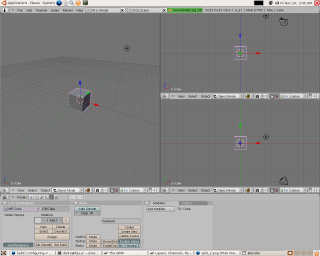
Click in the same place as you did above to pull down the hidden menu, but this time click on the RMB when your cursor is over the border.
You'll see something like this.
http://archive.flossmanuals.net/blender/_booki/blender/static/Blender-secret_menu-en.png
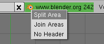 Choose Split Area by clicking the LMB once.
You'll see a light grey vertical line that follows the mouse cursor, extending right down the entire viewport.
Move it to the center of the viewport and click the LMB again.
You've just split the viewport into two, producing two new independent views of our future scene.
Now perform the same operation on the vertical split itself, this time producing a horizontal split in the rightmost viewport.
Once you've created a split you can move it around by simply LMBRMB on the edge between two and choose Join Areas.
A large arrow will appear giving you the option of choosing which viewport you want to join to the other.
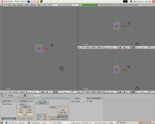
At the end, you should have something like this:
Choose Split Area by clicking the LMB once.
You'll see a light grey vertical line that follows the mouse cursor, extending right down the entire viewport.
Move it to the center of the viewport and click the LMB again.
You've just split the viewport into two, producing two new independent views of our future scene.
Now perform the same operation on the vertical split itself, this time producing a horizontal split in the rightmost viewport.
Once you've created a split you can move it around by simply LMBRMB on the edge between two and choose Join Areas.
A large arrow will appear giving you the option of choosing which viewport you want to join to the other.
At the end, you should have something like this:
Viewports and Axes
Note the small green and red arrows in the bottom of each viewport.
These are 2D axes that tell us what 3D elevation we are looking from.
That may sound complex at first, but it gets easier when you learn that these are fixed directions in Blender, and it's just a case of remembering them: positive Z points upward, positive Y points forward away from us, and positive X to the right of us.
A handy way of remembering this is to put your left hand in a shooting pose - like a gun - with the middle finger pointing to your right, your thumb pointing up and your index finger extending forward.
In this position the thumb is pointing along positive Z, your middle finger along positive X and your index finger along positive Y (this is a trick that's many centuries old).
Considering all this in terms of our viewports, we can look down at our scene from the Top view (down along Z onto Y and X), from the Front view (forward along Y onto Z and X ) or from the Side view (right along X onto Z and Y).
Looking at the viewport axes it's clear all our current viewports are all looking down at the object from the top (Y and X).
Let's change that to something more useful.
Change the top right viewport from Top to Front using the View menu at the base of that viewport.
Now change the left-most viewport to Side in the same way and, while you're there, from Orthographic to Perspective (ie.
from a mathematical rendering to a natural rendering mimicking the way we see objects).
Now the final touches.
Place your mouse cursor over the left-most viewport.
This is the way we tell Blender we're about to perform an operation just in that viewport (this is called Mouse FocusSelection).
Now press down on the MMB - yes, the wheel button itself - until it clicks.
Holding it down, drag downward with the mouse.
What you're doing is rotating that viewport around a center, this is how we roll a viewport in Blender.
We'll be doing this a lot in future sections..
Anyway, in the end you should have something like this:
 It'd be painful to have to do all this every time you start Blender, which is why we're going to save it as a default configuration so that next time it's ready just as we see it now.
To do this go to File --> Save Default Settings or just hit the CTRLKey+UKey and LMB click on Save User Defaults.
Be warned, when saving default settings, you don't only save the views and settings, but also the file that was opened.
Now learn a bit about Editing in Blender!
It'd be painful to have to do all this every time you start Blender, which is why we're going to save it as a default configuration so that next time it's ready just as we see it now.
To do this go to File --> Save Default Settings or just hit the CTRLKey+UKey and LMB click on Save User Defaults.
Be warned, when saving default settings, you don't only save the views and settings, but also the file that was opened.
Now learn a bit about Editing in Blender!
-Blender Interface
Note: Make sure you are familiar with Blender keyboard controls, and have configured Blender before going on with this chapter.
Basics
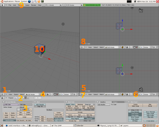
Let's get an overview of the interface itself.
Viewport Axes
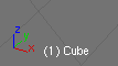 The above viewport axes represent the viewport is in Perspective View.
Note how there are 3 arrow axes and not just two.
We can see all 3 dimensions of an object when we're using this view, as opposed to just 2, for instance when looking in the Top, Front or Side views.
Another kind of view in Blender is Orthographic, which is less natural to our eyes (objects don't get small the further away they are in this view) but it's more mathematically representative.
The axes represented at the base of every viewport are what are known as global axes, in other words they are applicable for the entire scene and everything in it.
They cannot be altered, just in the same way East and West in the real world don't change direction.
The above viewport axes represent the viewport is in Perspective View.
Note how there are 3 arrow axes and not just two.
We can see all 3 dimensions of an object when we're using this view, as opposed to just 2, for instance when looking in the Top, Front or Side views.
Another kind of view in Blender is Orthographic, which is less natural to our eyes (objects don't get small the further away they are in this view) but it's more mathematically representative.
The axes represented at the base of every viewport are what are known as global axes, in other words they are applicable for the entire scene and everything in it.
They cannot be altered, just in the same way East and West in the real world don't change direction.
Panel type.
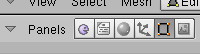 By clicking on these icons we can change settings relating to different primary functions in Blender.
Blender has several primary functions seen in those buttons.
In order they are:
Game Engine Logic buttons (F4-key)
Here we set up interactivity using buttons and connecting them together to create realtime interactive artworks.
Script Buttons This is for linking special scripts to Materials, Objects or whole Worlds.
Shading buttons (F5-key) Materials are created here and their properties manipulated.
This panel also contains sub-panels relating to light properties and the overall properties of worlds like atmospheric effects and physics.
Of note is that special materials can be assigned here for use in the Game Engine, called Dynamic Materials.
These change the way objects perform when in contact with other objects in the Game Engine.
Object buttons (F7-key) The properties of individual objects themselves are changed here, including settings relating to how objects perform when animated and their relationship to other objects when in motion (constraints).
This panel also contains a sub-panel where we can set physical properties for objects used when performing physical simulations.
Editing buttons (F9-key) When ever we're editing a mesh it's good to have this panel in view.
There are many settings here used when editing a form that change the way we edit it and allow us to change the properties of meshes themselves.
Here we can also turn off different visual indicators that help us understand detailed properties of our mesh just by looking at it.
Scene buttons (F10-key) Whenever we want to render out our work to make a picture or a movie, we use this panel.
Here are settings related not just to the format of our final creation (eg the size of the image or the filetype of the movie etc) but also how Blender should treat our scene when rendering it.
Of note is that there are two rendering plugins for use in Blender when you install it, the Blender Internal Renderer and the YAFRAY raytracing renderer which performs advanced calculations on the path of virtual light and so is often used to create very realistic visual effects.
By clicking on these icons we can change settings relating to different primary functions in Blender.
Blender has several primary functions seen in those buttons.
In order they are:
Game Engine Logic buttons (F4-key)
Here we set up interactivity using buttons and connecting them together to create realtime interactive artworks.
Script Buttons This is for linking special scripts to Materials, Objects or whole Worlds.
Shading buttons (F5-key) Materials are created here and their properties manipulated.
This panel also contains sub-panels relating to light properties and the overall properties of worlds like atmospheric effects and physics.
Of note is that special materials can be assigned here for use in the Game Engine, called Dynamic Materials.
These change the way objects perform when in contact with other objects in the Game Engine.
Object buttons (F7-key) The properties of individual objects themselves are changed here, including settings relating to how objects perform when animated and their relationship to other objects when in motion (constraints).
This panel also contains a sub-panel where we can set physical properties for objects used when performing physical simulations.
Editing buttons (F9-key) When ever we're editing a mesh it's good to have this panel in view.
There are many settings here used when editing a form that change the way we edit it and allow us to change the properties of meshes themselves.
Here we can also turn off different visual indicators that help us understand detailed properties of our mesh just by looking at it.
Scene buttons (F10-key) Whenever we want to render out our work to make a picture or a movie, we use this panel.
Here are settings related not just to the format of our final creation (eg the size of the image or the filetype of the movie etc) but also how Blender should treat our scene when rendering it.
Of note is that there are two rendering plugins for use in Blender when you install it, the Blender Internal Renderer and the YAFRAY raytracing renderer which performs advanced calculations on the path of virtual light and so is often used to create very realistic visual effects.
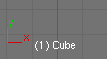
Object Name
Viewport Shading Type
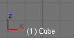
Example of axes seen in Top view.
 Take note of the two global axes in this view, one is Y and one is Z.
Think of those two axes as representing the ground under your feet.
Y points in front of you and X to the right of you.
Take note of the two global axes in this view, one is Y and one is Z.
Think of those two axes as representing the ground under your feet.
Y points in front of you and X to the right of you.
Transform Manipulators.
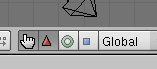 By choosing a Transform Manipulator like Rotation (represented in Blender as a circle) and then selecting an axis, the currently selected object can be rotated around that axis like a wheel on an axel.
Similarly by choosing the Translation manipulator we can click on an axis and drag the current selection along it, as though it were on rails.
In 3D terminology 'translation' means "moving through space".
Often confusing, but translation in this sense has nothing to do with language.
The other manipulator often used is the Scale manipulator.
This is useful if you want to quickly (but innacurately) scale a form along one or two axes, in other words, perform a non-uniform scale.
By choosing a Transform Manipulator like Rotation (represented in Blender as a circle) and then selecting an axis, the currently selected object can be rotated around that axis like a wheel on an axel.
Similarly by choosing the Translation manipulator we can click on an axis and drag the current selection along it, as though it were on rails.
In 3D terminology 'translation' means "moving through space".
Often confusing, but translation in this sense has nothing to do with language.
The other manipulator often used is the Scale manipulator.
This is useful if you want to quickly (but innacurately) scale a form along one or two axes, in other words, perform a non-uniform scale.
Window Type Button.
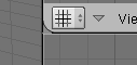 By clicking this button a list of different 'window types' are displayed.
There are many in Blender each of which are responsible for giving us access to core functionality within the program.
When you select an item from that menu the current split window will change type.
For instance clicking on Video Sequence Editor will change the window from a 3D Viewport to a window for laying out video tracks in time.
As you can see, there are many other window types, including a Sound Sequencer, a Text Editor (also used for writing Python scripts), IPO Curve Editor (used to animate objects with great detail), schematic views (giving you a diagram of your scene) and more.
By clicking this button a list of different 'window types' are displayed.
There are many in Blender each of which are responsible for giving us access to core functionality within the program.
When you select an item from that menu the current split window will change type.
For instance clicking on Video Sequence Editor will change the window from a 3D Viewport to a window for laying out video tracks in time.
As you can see, there are many other window types, including a Sound Sequencer, a Text Editor (also used for writing Python scripts), IPO Curve Editor (used to animate objects with great detail), schematic views (giving you a diagram of your scene) and more.
An axis seen in Front view.
 Imagine in this case the cube represented is a building.
You're standing on the ground looking at it front on.
The global axes represented are Z and X.
This means that global Z points up, which it always does in Blender.
Imagine in this case the cube represented is a building.
You're standing on the ground looking at it front on.
The global axes represented are Z and X.
This means that global Z points up, which it always does in Blender.
Main operation menu
An object
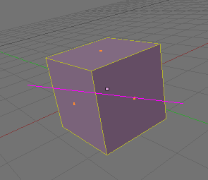
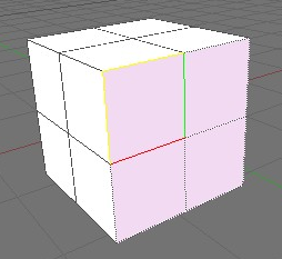
 Here is a cube, in Edit Mode, seen in Perspective view, with a Translation 3D Transform manipulator active and with one vertex selected.
The important thing to note here is the axes right on top of that vertex.
These axes, despite 'mirroring' the directions of the viewport axes in this case, are actually local axes, not global axes.
In this case, they show us the orientation of our selected vertex; a single point in 3D space.
Put simply, every object - even parts of objects - has its own orientation and these orientations are always in relation to the fixed directions of the world.
This understanding of the difference between local and global axes applies right across all of geometry and any 3D software package.
Here is a cube, in Edit Mode, seen in Perspective view, with a Translation 3D Transform manipulator active and with one vertex selected.
The important thing to note here is the axes right on top of that vertex.
These axes, despite 'mirroring' the directions of the viewport axes in this case, are actually local axes, not global axes.
In this case, they show us the orientation of our selected vertex; a single point in 3D space.
Put simply, every object - even parts of objects - has its own orientation and these orientations are always in relation to the fixed directions of the world.
This understanding of the difference between local and global axes applies right across all of geometry and any 3D software package.
Two core interface modes
One of the best ways of approaching Blender for the first time is in the context of its modes.
When you change modes, the interface changes with it, not just what you see (menus and the look of your artwork) but also the key combinations that are available to you.
The menu at the base of every 3D viewport is where we change modes relating to editing.
It looks like this:
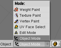 Of these modes there are two you'll be using a lot: Object Mode and Edit Mode.
Both of these modes do quite different things.
Of these modes there are two you'll be using a lot: Object Mode and Edit Mode.
Both of these modes do quite different things.
Edit Mode
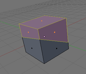
Edit Mode is used to modify the form of an object, including properties relating to that form. Examples of this might be cutting an object in half, twisting it like rubber or adding more detail to a part of the overall form. Whenever you want to reshape an object, manipulating its form, use Edit Mode. This is what Edit Mode looks like. You can see how the 3D form in the Viewport (herein called a mesh) looks translucent and has dots on every corner. These dots are called vertices, the lines that join them are called edges and the flat surfaces that 3 or more vertices and edges make together are called faces - commonly also known as polygons or just polys. The currently selected element in this image is a single vertex, but it could just as equally be an edge, face or several of them altogether.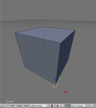
Object Mode
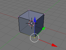
Object Mode deals only with the properties relating to the object itself, like its name, its location, its size and its relationship to other objects (ie. parent and child objects). When ever you want to move an object, add a new object, rename an object or change other aspects relating to its 'objecthood', use Object Mode. This is what a viewport looks like in this mode. Notice how the coloured axes are attached to a dot in the center of the mesh? This is because the whole object is selected, and so they are located at the object center.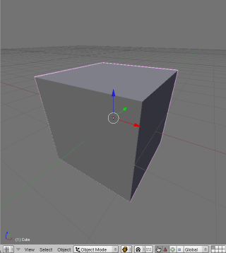
The fastest way of moving between these two modes is with the TAB. Hitting it simply switches between modes, from one to the other and back again. Placing your cursor over a viewport (this is how we tell Blender which viewport to use) try hitting TAB a couple of times. Notice how several other things also change in the interface? The whole Button panel at the base also changes.
Let's not edit anything yet however until we've gotten used to using the mouse in Blender..
Mouse input
As mentioned in the introduction, Blender distributes mouse input over three buttons in a mouse by turning the wheel itself into a button. Firstly let's learn about the roll, something intrinsic to navigating a 3D scene.
Roll
Place your cursor over a viewport and press the MMB until you feel it click and then drag the mouse around. You'll see the object turning in the viewport. In fact it's not the object that's rotating, but the view itself, like a camera orbiting around the object. It may seem unusual to use the mouse-wheel as a button, but it's effective once you get used to it.Pan
Panning is when you take whatever view you have of the object and scroll that view, from left to right or up or down. Your orientation in relation to your object doesn't change during the process however. This is really handy for moving around your scene. To Pan press SHFT+MMB and drag your mouse around. You'll see the object scrolling in the direction you drag the mouse.Zoom
Zooming is no different to how it would be were you using a camera. The view direction is fixed but you move the viewing point closer to or further away from the object. You can zoom just using the wheel like you would normally, but if you want a really smooth zoom, try CTRL+MMB and dragging up and down on your mouse. Smooth zoom gives you much greater control over the zoom distance and is worth getting used to.
Selecting and Moving
Lets try moving our cube a little bit, just to get used to using the mouse and keyboard together.
In your scene at the moment is a camera, a light and a cube.
The camera is the pyramid shaped object and the light is the line with the circle on the top.
Zoom out so you can see all of your cube in the left most 3D viewport.
Make sure there's some room to the left and right of it.
Ensure you're in Object Mode.
The cube should have a pink outline around it, as seen in the above image.
When an object is pink, it's selected.
Hit the A-key once and then once again.
Notice how everything becomes pink and then black the second time? A-key is the shortcut for select all and select none.
You can also use the Select menu to access this feature, named Select/Deselect All.
Making sure nothing is selected RMB click once on the cube.
Then, with your mouse cursor still over that viewport, hit the G-key once and move your mouse around.
The object will follow the mouse.
'G' in G-key stands for grab.
When you hit this key you're tellling blender to lock the currently selected object to the mouse cursor.
Now hit ESC or hit the RMB again, the object will snap back into it's original location.
Let's try this again but this time let's move the object and give it a new location.
To do this, repeat the above steps of grabbing the object but instead of clicking RMB at the end, click the LMB.
This tells Blender, "put the object there and leave it there".
You can also use the cursor keys in grab mode instead of the mouse.
To place the object where you want it, just hit ENTER.
Some of you will be familiar with the concept of snapping, which is moving the object to units on a grid, one at a time.
This is often used by people that need really accurate results.
To move an object and have it snap to grid units, hold CTRL down while you move the object.
This also works perfectly well with the cursor keys.
Now place your mouse cursor over the viewport with our Top view.
LMB once next to the cube you already have in the scene.
Notice the small red circle that follows the mouse click.
Click around, it will follow.
It looks like this.
At any time you can center the 3D cursor by hitting SHFT+C-Key.
The 3D cursor defines where new objects are added.
Centering it places it at the location x=0, y=0, z=0.

This is an important tool, known as the 3D Cursor. Wherever this cursor is in the scene is where new objects will appear. It's also important for other reasons I'll show you later. OK, let's add an object.-
Adding New Objects
Blender provides a variety of basic objects (often called primitives) for us to manipulate in the course of modeling. While it is certainly possible to make a model from scratch (adding three vertices and making a polygon from them) it is often more useful to start with an object that has properties we need in order to most quickly build our model. For instance, if you were modeling a chair you'd start with a cube or plane primitive. If you were modeling a pear or cat head, you'd be better start with a sphere primitive.
Move the 3D cursor to a location just left of the current cube in a Top View. Checking once again that you're in Object Mode - and with your mouse cursor over the viewport in Top view - hit the space bar and move the mouse to move across the menu entries Add->Mesh->Cube. Now hit ENTER or LMB. You should now have two cubes in your scene. Notice though that the Cube you've just added is added in Edit Mode. It won't respond like the other cube, and we can't safely move it in its current mode, only edit the mesh itself. To move it safely, go into Object Mode either by using the mode button at the base of the viewport, or hitting the TAB.
Note: you can not edit the meshes of more than one object at the same time. Object mesh data is accessed and managed on a per-object basis.
Selecting individual objects.
Each object contains its own data. An object's data includes its name, its mesh, its editing history, its location, its textures (and more). It is important to remember that an object's mesh is just a part of that object's data. When you are moving the mesh around, you are not moving around the object. Similarly, you can delete all the mesh data from an object and the object will still exist. It merely has no mesh. Once in Object Mode, RMB to select either of the two objects. Now hit G-key as you did earlier and move it around. As you can see objects must be first selected before they can be manipulated. Notice also that as you move objects around in the Top or Front view, they move around at the same time in the Perspective view. Have a play with that for a bit and then as a next step consider editing using various techniques.
Mesh Editing Quickstart
Important - Make sure you understand the Blender Interface before going on with this ch-apter.
For those of you that simply want to get started m-odeling your own projects, I'm going to give coverage of basic techniques common to most 3D modeling software.
Later on, I'll take you through the process of making a model step by step using some of these techniques.-
First, ensure you have an object in your scene.
If you don't have one yet, add a Cube (see Interface section for how) or just use the default Cube that Blender provides when you start it up.
Selection Modes
Hit the A Key on your object to ensure that no vertices, faces or edges are selected.
A deselected face is blue in colour.
Note that in the bottom of the viewport - and only while in Edit Mode - are a few icons that look like this:
Global and Local Axes
Many of the below editing techniques refer to the axes X, Y and Z.
Before working with axes in a 3D environment it's important to remember that objects and faces can have both Local and Global axes.
Global axes are applicable to the entire scene and everything in it.
They cannot be altered, just in the same way East and West in the real world don't change direction.
Local axes however represent only the orientation of an object or part of an object in question.
Local axes can be thought of as being a bit like in front, behind, to the left and to the right.
Local axes are relative, in that they depend upon which way the object is facing.
For instance an object might have its Local X axis pointing along the Global Z axis.
Before applying a transformation (like Rotation or Scaling etc) decide whether you want to perform it using the local orientation of your selection, or the global orientation of your scene.
You can change whether you're working within the Global or Local orientation using the Transform Orientation drop-down menu at the base of each viewport.
This menu is shown in the below image:
Rotating
Free Mouse rotation
Any selection of faces can be rotated using the R-key followed by free mouse movement. Naturally this is highly innacurate, especially if done in a Perspective view.Numeric rotation
Faces can also be rotated along a given axis by a numerically defined number of degrees. To do this first select the faces you'd like to rotate, hit the R-key then hit the axis you'd like to rotate around and then enter a number of degrees. For example, if I wanted to rotate a face around the global Z axis by 45 degrees I'd: R-key then Z-key then NUMPAD-4 then NUMPAD-5. Important: when you rotate objects or meshes using numeric input you are rotating those parts relatively, not absolutely! For example: R-key then Y-key then 45NumPad means "rotate around the Y axis another 45 degrees".
Uniform and Non-Uniform scaling
Uniform scaling refers to the method of scaling the selection by the same amount across all axes at once.
This is the default in Blender.
Non-uniform scaling is the term given to selective scaling across just one or two of the axes.
For example, to make an object twice as long as it is wide or high you could non-uniformly scale it along just one axis.
Uniform scaling: mouse
Doing this with the mouse is quite tricky but is very convenient once you become familiar with it. This technique involves telling Blender which axis you want to scale along using a mouse gesture. Select all or some faces in your object (selecting all will make this excercise clearer). Now move your mouse cursor along the axis you want to scale your faces and then press the MMB down. The faces will scale along that axis only. For instance, if you wanted to scale your entire mesh only along the Y axis you'd switch to Top view (orthographic of course), move the mouse in the up-down direction and then hit MMB. As usual, ENTER or LMB will confirm the change.Non-uniform scaling: numeric
This technique is very similar to the numeric uniform scaling above, but involves telling Blender which axis you want to scale along. Select the faces you want to scale, hit the S-Key, choose an axis and then provide the scale multiplier number. For example: to scale twice along the Z axis you'd: S-Key then Z-key then NUMPAD-2.Non-uniform constrained scaling: numeric
It is also possible to tell Blender to scale along all except one axis. To scale along the X and Y axes while denying scaling along Z you'd: S-key then hit SHFT+Z-key then NUMPAD-2.
Selecting Regions
Two marquee like selection modes are provided.
These are especially useful for selecting vertices and/or faces in detailed meshes.
They can also be used to select several objects in object mode.
Naturally this technique will be most useful to you when there are many vertices in your object.
Select your object and go into Edit mode.
Box Select
With your cursor over the viewport you want to select in, hit the B-key. Note that the mouse cursor changes to a cross-hair, with perpendicular dotted lines extending from it. Now you can LMB and drag a selection marquee across mesh elements of your object. ESC will exit Box select mode.Circle Select
Hitting B-key twice enables circle select mode, enabling you to select using a circle shape instead of a square. Using the wheel on your mouse while in this mode will increase or decrease the size of this selection area. ESC will exit circle select mode.
Creating and Deleting Vertices, Edges and Faces
Deleting vertices, edges or faces.
Often in the course of editing you will want to remove elements. You may, for example, wish to remove a face but leave just the edges or just delete everything in the selection altogether. To do this simply select the area you wish to delete from and hit DEL or X-key. A popup menu will appear providing you with a list of deletion options. Choose one with the mouse or arrow-keys and hit LMB or ENTER.Creating vertices, edges or faces without duplication.
Blender can be used to 'draw in' new mesh elements very quickly. There are several ways to do this. I will cover the most commonly used here.Adding vertices
Holding the CTRL key down while you LMB in a viewport will add vertices under the cursor. These vertices will be connected by edges.Adding a single face
Both edges and faces depend on vertices. Edges need two vertices to exist and faces a minumum of three. To add a single face, do one of the following: Select any three or four vertices and hit the F-key. A face will automatically be created. Select any two edges or any three contiguous edges and hit F-key. Thre non-contiguous edges will not make a face, instead you'll get a popup asking if you'd like to make an FGon (a special surface).Adding multiple faces
Select a loop of edges and hit SHFT+F-key. By a loop of edges I mean a ring connected edges (a circle being a good example). A 'U' shape of edges cannot be used to create multiple faces: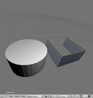 Multiple faces were added to the top of the cylinder at once using SHFT+F-key.
This cannot be done to the open form without adding a closing edge.
Multiple faces were added to the top of the cylinder at once using SHFT+F-key.
This cannot be done to the open form without adding a closing edge.
Subdividing
Single or multiple faces can be subdivided in a variety of different ways.
First, select the faces you want to subdivide.
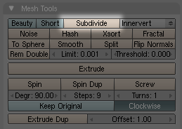
In the Editing panel F9-key click the button subdivide.
Each time you click the subdivide button, the selected faces will be cut in half.
Next to this button are a variety of subdivision types in a dropdown menu.
Extrusion
Extrusion is a very popular editing method used often in the practice of mesh modeling.
Unlike many other methods extrusion actually adds mesh data to the original mesh.
Faces, edges and even vertices can be extruded.
Note:
If you extrude a face of 4 edges, 4 more faces will be created, once for each 'side' of the new extruded part.
If you extrude an edge, one more face will be created.
If you extrude a vertex, one more edge will be created.
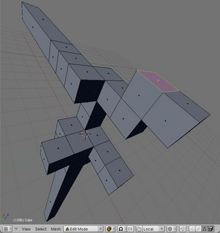 A cube with one face and two edges extruded and a subdivided cube with many faces extruded.
Extrusion: mouse
To extrude a single face, select the face and hit E-key then move the mouse. The face will extrude along the Normal (eg perpendicular to the surface of the face). Holding the CTRL key down while moving the mouse will constrain (lock) the extrusion to grid-units.Extrusion: numeric
Select a face, hit the E-key and then provide a number. For instance to extrude a face two whole grid units along its normal you'd E-key then NUMPAD-2 then ENTER to confirm the transformation.
Cutting Meshes
Often it is useful to cut one or more faces in half.
For this purpose Blender provides the Knife tool.
First select the faces you wish to cut and hit the K-key.
You will immediately be presented with a popup menu containing several options:
Knife (exact).
This will cut the selected faces across exact points on each edge in the cut.
Use this option if you want to make accurate cuts.
Knife (midpoints).
This will cut the faces once exactly in half across the midpoints of each edge in the cut.
Use this option if you simply want to cut a face in half.
Knife (multicut).
This allows the user to cut the selected faces several times at once.
The cuts will be at midpoints, eg.
a face cut four times will produce a total of five faces of equal size.
Knife (loop cut).
This will cut all faces (selected or not) in half throughout the mesh along a local axis determined by mouse-movement.
This is very useful for cutting whole meshes in half.
If you choose to make an exact, midpoints or multicut, simply click once to one side of the faces you want to cut, and again on the other side, then hit ENTER.
The below images show an exact cut in use.
Before and after images of the Knife tool making an exact cut. To make a loopcut, just move the mouse around until you see the cut you'd like and hit ENTER.
Separating ('parting') Faces
Sometimes it's useful to be able to separate a selection of faces from others in a mesh, creating a new object.
To do this use the P-key.
To remember this shortcut, I like to think of 'P' as representing 'part'.
New objects will be automatically given a new name based on the name of the original object.
This function can be found in the Mesh->Vertices menu at the base of the viewport or under the spacebar menu.
Duplication
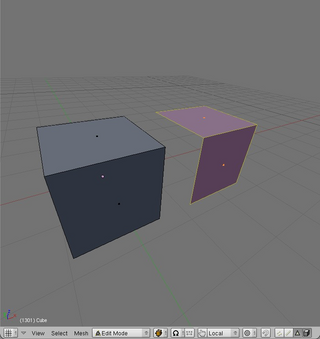
Selected faces, edges or vertices can be quickly duplicated using SHFT+D-key.
Once they have been duplicated they are automatically in grab mode, so be sure to move the mouse and place the copy elsewhere.
If you don't do this, the duplication will remain exactly where the original is, and you won't know it's there!
The below image shows two faces copied from the original cube and moved one unit to the right:
Joining Objects
One object can be joined to another (thus creating a new object) using CTRL+J-key.
This function can be found in the Object menu at the base of the viewport or under the spacebar menu.
Smoothing Meshes and Surfaces
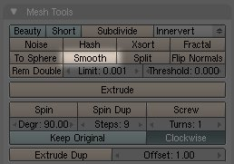
Pressing the smooth button in the Mesh Tools tab in the Editing panel will give a mesh a more organic feel by simply increasing the angles between groups of vertices.
The more times you press the button the smoother the mesh will become.
Naturally, the more vertices the smoother it can become.
The below image shows where the Smooth button is be found.
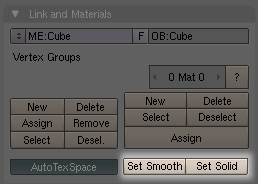
 Note: Smooth is not to be confused with Set Smooth which applies a setting to the surface so that shading is averaged out across ajoining faces during rendering.
Set Smooth is the opposite of the Set Solid setting, which performs no shadow averaging between faces.
To make things a little confusing, this setting is also found in the Editing panel, but under the Link and Materials tab:
Note: Smooth is not to be confused with Set Smooth which applies a setting to the surface so that shading is averaged out across ajoining faces during rendering.
Set Smooth is the opposite of the Set Solid setting, which performs no shadow averaging between faces.
To make things a little confusing, this setting is also found in the Editing panel, but under the Link and Materials tab:
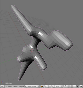
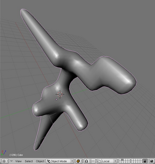
 Below shows heavily subdivided version of the above extruded form mesh smoothed 10 times in both Set Solid (default) and Set Smooth surface modes:
Cleaning Up
Often in the course of editing in Blender little accidents happen that result in duplicate vertices.
One common example of how this can happen is during extrusion: you select a face to extrude and hit the E-key but change your mind, and so cancel the extrusion.
You've just created an entire face sitting right ontop of the other.
Another example might be that you select your entire mesh with the A-key and then duplicate it with SHFT+D-key.
Instead of moving it to a new location you leave it sitting right where the original is leaving many duplicate faces (and so duplicate vertices and edges) invisible to the eye.
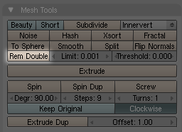
It's good practice to clean up these duplicate vertices using the Rem Doubles ('remove doubles') button.
This function looks for vertices within a given distance from each other and if they are within this distance, it removes one of them and moves the remaining one half way between the other two.
When set to a very small number (the default is fine) this can be very effective in cleaning up a mesh.
The Rem Doubles button can be found just below the Subdivide button in the Mesh tools tab in the Editing (F9-key) panel.
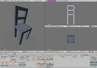
Basic Mesh Editing
Keywords: extrusion, positioning, face creation, face duplication, low-polygon modeling, view management.
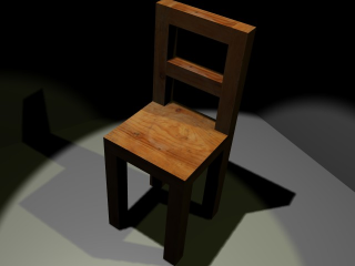
In this lesson we'll make a simple chair starting from a single plane using techniques written above in the Mesh Editing Quickstart Guide.
I chose a chair for this lesson as it's is a familiar object that encompasses 3 dimensions in a way we can easily visualise (unlike spaceships, demon warriors or contemporary architecture).
Firstly ensure you have nothing in any of the three views.
You can do this by either changing to another layer, or (in Object Mode) select everything with A-key and hit DEL.
Now put the left viewport into Top/Orthographic view, the upper right viewport in Side/Perspective view and the bottom right viewport in Side/Orthographic view.
Top/Orthographic can be thought of as a plan view, which is ideal for layouts and floorplans.
Important: when you're working in a top or side view set to Orthographic two dimensions are visible, not three.
This significantly reduces confusion (and therefore error) whenever positioning objects or mesh elements with the mouse.
If ever unsure check it in the View Menu in the base of each viewport.
With your cursor over a viewport, center the 3D cursor with SHFT+C-key.
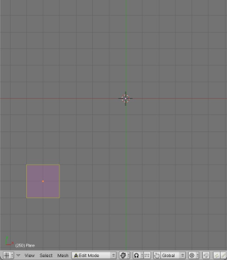
Hit the spacebar and Add->Mesh->Plane.
A plane will appear where the 3D cursor is and Blender will be in Edit Mode.
This plane will become one of four legs.
Choose Face Select and select that face if it isn't already.
Now we want to move that plane to the right and down a few units (x = 5, y = -5).
There are three ways to do this:
Moving it with the mouse:
Hit the G-key and then hold down CTRL while moving the mouse 5 grid-units to the right and 5 down after that.
Moving it with the keyboard:
To do this numerically (ie without having to count the grid units visually), hit the G-key then X-key then type 5 on the numeric keypad and hit ENTER.
Now the Y axis: G-key, Y-key- and then 5 on the numeric keypad and hit ENTER.
Important: when you move objects or meshes using keyboard input you are moving them relatively, not absolutely! In the above example we moved the plane down 5 units and across 5 units.
If you want absolute positioning, use the Numeric interface (see below).
Moving it using the numeric interface:
Hit the N-key and enter the relative X and Y values manually.
The advantage of the numeric interface is that we can move the objects to absolute locations.
Moving it using the 3D transform manipulator and the mouse:
Click on the 3D Transform manipulator at the base of the viewport you're working with and click on the triangle icon to allow for Translation (re-positioning).
Now click the axis you'd like to move the plane along and drag with the mouse.
Note: Choose the way of moving objects most comfortable for you and use it to move objects elsewhere in the Blender tutorials.
You should now have something that looks like this in your Top view:
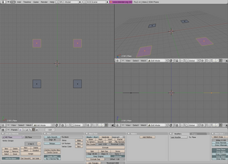
 Now duplicate that plane with SHFT+D-key and move it along negative X by 10 units (x = -10).
The new position of this plane is therefore (x = -5, y =-5).
We have two feet for our chair and we need four, so duplicate this pair of planes and move it up 10 whole grid unit.
Here's what my chair looks like so far:
Now duplicate that plane with SHFT+D-key and move it along negative X by 10 units (x = -10).
The new position of this plane is therefore (x = -5, y =-5).
We have two feet for our chair and we need four, so duplicate this pair of planes and move it up 10 whole grid unit.
Here's what my chair looks like so far:
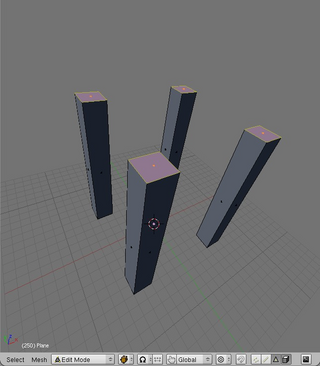
 It's time to extrude all four of these feet to create legs.
We'll do this in the Side view as we can't extrude 'upward' in the Top view.
Up is along the Z axis, which is the axis not available to us in the Top view.
Select all the feet and in your side view hit E-key, choose Region then type 15 on the numberpad and hit ENTER.
This will extrude those planes 15 grid units.
This is what I have after doing this:
It's time to extrude all four of these feet to create legs.
We'll do this in the Side view as we can't extrude 'upward' in the Top view.
Up is along the Z axis, which is the axis not available to us in the Top view.
Select all the feet and in your side view hit E-key, choose Region then type 15 on the numberpad and hit ENTER.
This will extrude those planes 15 grid units.
This is what I have after doing this:
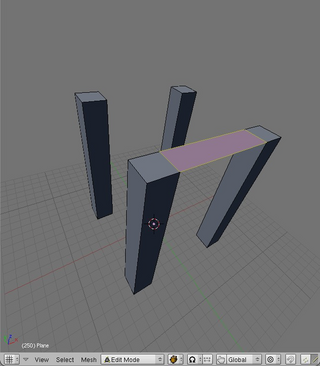
 It's time to create some faces, so let's change the leftmost viewport into Perspective view so we can better see what we're doing.
Make sure this viewport is in Solid draw mode.
With your cursor over the viewport with the Perspective view hit NUMPAD-5.
If you have a small screen you can make this viewport larger by dragging over the split between viewports.
Note: Alternatively you can hit CTRL+UpArrow (or use View->Maximise Window) to maximise the viewport under the cursor.
Pressing the same key combination again will take you out of maximised view.
The disadvantage of a maximised view is that you can't see the Edit Panel or other viewports while in this mode.
Switch to Edge Select mode and select the innermost edges at the top of two legs and hit the F-key to create a face there.
It looks like this:
It's time to create some faces, so let's change the leftmost viewport into Perspective view so we can better see what we're doing.
Make sure this viewport is in Solid draw mode.
With your cursor over the viewport with the Perspective view hit NUMPAD-5.
If you have a small screen you can make this viewport larger by dragging over the split between viewports.
Note: Alternatively you can hit CTRL+UpArrow (or use View->Maximise Window) to maximise the viewport under the cursor.
Pressing the same key combination again will take you out of maximised view.
The disadvantage of a maximised view is that you can't see the Edit Panel or other viewports while in this mode.
Switch to Edge Select mode and select the innermost edges at the top of two legs and hit the F-key to create a face there.
It looks like this:
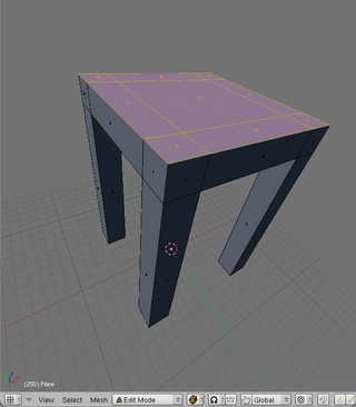
 Starting with the top of the legs, create faces across the remainder of that area, so that it looks like so:
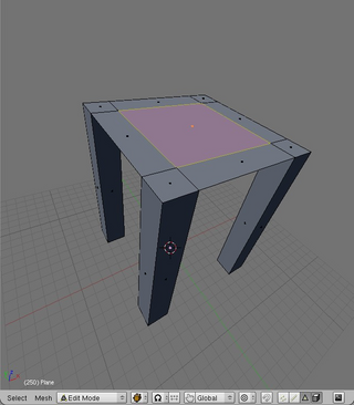 Now we have the base of the seat, so let's extrude it up.
Change to Face Select mode and select all the faces on the base of the seat.
Extrude them all upward by 2 grid units.
Now we have the base of the seat, so let's extrude it up.
Change to Face Select mode and select all the faces on the base of the seat.
Extrude them all upward by 2 grid units.
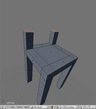
 Select the two back faces at the top of the legs, and extrude them up too, by 5 grid units:
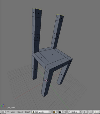
 Extrude them up again, by another 2 grid units and then up again by another 5 and then finally another 2 units.
You should have something that looks a bit like this:
Extrude them up again, by another 2 grid units and then up again by another 5 and then finally another 2 units.
You should have something that looks a bit like this:
 Now we'll make the back of our chair by extruding over two cross-beams.
Select the two innermost square faces on one leg and extrude them over by 8 grid units along negative X so that they neatly touch the complimentary faces on the other leg.
Remember that holding down CTRL while moving the mouse will constrain it to the grid.
Alternatively, just use the numeric keypad (E-key then X then -8 on the numeric keypad and then ENTER).
Now we'll make the back of our chair by extruding over two cross-beams.
Select the two innermost square faces on one leg and extrude them over by 8 grid units along negative X so that they neatly touch the complimentary faces on the other leg.
Remember that holding down CTRL while moving the mouse will constrain it to the grid.
Alternatively, just use the numeric keypad (E-key then X then -8 on the numeric keypad and then ENTER).
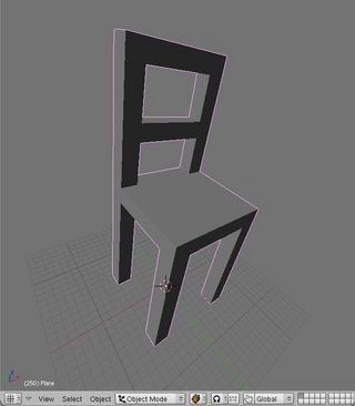
 Before we can finish we have to clean up a little.
That last extrusion has created a couple of redundant faces in our mesh: we pulled over faces from one leg right ontop of another.
Select all the mesh with A-key and hit the button Rem Doubles in the Mesh Tools tab in the Edit Panel.
For a description of how Rem Doubles works see Cleaning Up above.
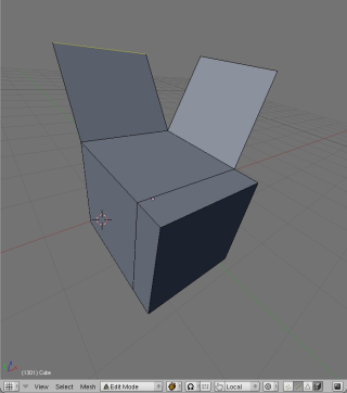
Once done, go into Object Mode and take a look at your creation.
Here's how mine turned out:
Before we can finish we have to clean up a little.
That last extrusion has created a couple of redundant faces in our mesh: we pulled over faces from one leg right ontop of another.
Select all the mesh with A-key and hit the button Rem Doubles in the Mesh Tools tab in the Edit Panel.
For a description of how Rem Doubles works see Cleaning Up above.
Once done, go into Object Mode and take a look at your creation.
Here's how mine turned out:
 As a next step you may consider applying textures in Blender and then texture your chair.
Head over to the Texturing section to learn how to do this..
As a next step you may consider applying textures in Blender and then texture your chair.
Head over to the Texturing section to learn how to do this..
Blender Texturing
In this section we'll learn about basic texturing in Blender.
This section will not cover Materials in any d-epth.
Instead we'll focus only on getting raw images onto faces in your mesh, lighting the mesh and rendering the result.
The reasons for this are two-fold: materials are a complex topic and what we do here will be sufficient for use in realtime 3D projects - ie the Blender Game Engine.
I'll dedicate a section to working with Materials and advanced Rendering later on.
Faces have a shape, a size, a position in space and even a local orientation.
None of these things however help us define how textures are drawn onto the surface on those faces.
For this we need a system dedicated to mapping texture data onto the mesh surface.
This is why UV mapping was invented.
A mapping is best understood as an imaginary 2D or 3D shape onto which the texture is first projected before it is applied to the mesh itself.
By changing the projection type we change the way textures are drawn onto the surface.
Once we have chosen a UV Mapping we can manipulate it (scale, rotate, edit etc) independently of the mesh itself, thus changing the way the texture is drawn on the actual mesh surface.
A simplistic way of understanding this is that 'U' and 'V' in 'UV Mapping' are special values describing positions on the surface of a given mesh, just like X and Y are positions on an imaginary plane in the 3D world itself.
The most basic UV Mapping is a per-face mapping, where the texture is simply drawn onto each face in the mesh; this is the default in Blender.
Other UV mapping types are covered below.
Setting up a mesh for texturing requires understanding the Texture Face tab in the Editing panel.
UV settings are defined in the Editing panel because we are editing a property of the mesh, ie its UV data.
Selecting Faces
Previously we've worked with the modes Object Mode and Edit Mode.
Using the same Mode menu at the bottom of a 3D viewport, or with the F-key, change to UV Face Select Mode and ensure you're using the Textured viewport shading type.
![]() Select a face in your mesh with the RMB or other selection method.
The face is now 'active', meaning it is ready for the assignment of settings and textures.
Note: Selecting a face is not the same as making that face active.
There is always only one active face in any UV Face selection.
When a face is active it has coloured edges.
In the below image there are four faces selected but just one is active:
Select a face in your mesh with the RMB or other selection method.
The face is now 'active', meaning it is ready for the assignment of settings and textures.
Note: Selecting a face is not the same as making that face active.
There is always only one active face in any UV Face selection.
When a face is active it has coloured edges.
In the below image there are four faces selected but just one is active:
 Faces can also be selected in UV Face Select mode using various selection methods.
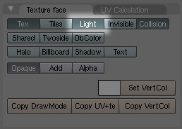
Setting faces up to receive light
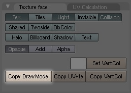
With the face active, click the In the Texture Face tab in the Editing panel (F9-key) and click the blue/green button labeled Light.
Apply these settings to other faces using the method described in "Copying settings from one face to another" (below).
 Now in a Top view add a light from the spacebar menu and place it right above the face you've selected.
You can move the light around and the shading on the meshes will respond accordingly.
Important: without a light in your scene, and your faces set up to receive light, your mesh will have no shading in all viewports in Textured shading mode! This is almost certainly not what you want.
Now in a Top view add a light from the spacebar menu and place it right above the face you've selected.
You can move the light around and the shading on the meshes will respond accordingly.
Important: without a light in your scene, and your faces set up to receive light, your mesh will have no shading in all viewports in Textured shading mode! This is almost certainly not what you want.
Applying a texture
Change the current window type in one of your splits to UV/Image editor.
Ensure you are in UV Face Select mode and have made a face active.
Load a texture using Image->Open in the UV/Image Editor window and it will appear on your active face.
Important: texture data will only be visible in your viewport if it is set to the Textured shading mode.
You can load any number of textures this way and change between them using the dropdown menu at the base of the UV/Image Editor menu.
Each time you select a texture from this menu it will appear on the face you have active in UV Face Select mode.
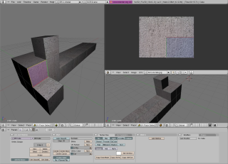 A lit and textured mesh with one face active in UV Face Select mode.
Note: one texture is applied per face (ie no UV Projection has been set).
Selected faces will appear in the UV/Image Editor window.
Without any projection type applied (eg one texture per face), they will be drawn one-ontop-of-another in the UV/Image Editor, and so won't be easily discernable from each other.
A lit and textured mesh with one face active in UV Face Select mode.
Note: one texture is applied per face (ie no UV Projection has been set).
Selected faces will appear in the UV/Image Editor window.
Without any projection type applied (eg one texture per face), they will be drawn one-ontop-of-another in the UV/Image Editor, and so won't be easily discernable from each other.
Copying settings from one face to another
Texture and UV settings can be copied from the active face to any other selected faces using Copy Draw Mode.
Simply make the face you want to copy settings from active, select any number of other faces and click the Copy Draw Mode button, which is found in the Texture Face tab in the Editing (F9-Key) panel.
UV Projection types
While in UV Face Select mode you can easily apply a new projection using the UV Calculation menu accessed with the Ukey.
Here you'll find a variety of different projection types:
Unwrap
The projection surface is an imaginary 'unwrapped' version of the mesh, such that faces are distributed on a 2D plane with as little distortion or overlap as can be computed.
A texture is then projected onto this surface.
This is the method used for highly accurate texturing work.
A good way of imagining unwrapping is the flat atlas of the Earth, which is an unwrapped sphere featuring as little distortion as is mathematically possible.
This particular unwrapping has the name Goodes Interrupted Homolosine Projection.
Cube
Projects the texture onto an imaginary cube first each of which are parallel to Global axes X, Y or Z.
It will then find all the faces in the real mesh aligned most closely to the six sides of this cube object and draw the texture onto the faces accordingly.
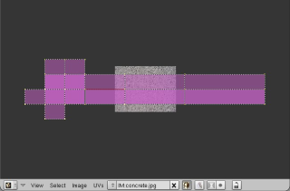
Image shows a Cube Projection of a mesh with all faces selected in UV Face Select mode. Cylinder from View Cylinder from View first maps a texture onto a cylinder that has the same orientation as the viewport before projecting it onto the active face Sphere from View Sphere from View first maps a texture onto a sphere that has the same orientation as the viewport before projecting it onto the active face Project from View Project from View maps a texture onto the viewplane in every repeating tiles and then projects it straight onto the active face. Project from View (bounds) Note the 'from View' in the above projections. This means that the given projection types are projected onto the mesh perpendicular to the viewplane. To understand this, imagine that the viewport you are looking through is the lens of a camera. The viewplane is an infinitely large imaginary plane flush to the surface of that lens (ie. parallel to the tangent of the viewport).
Modifying UV Mappings
Every UV face in the current selection is represented in UV/Image Editor.
These faces are manipulated much in the same way as meshes are: they have vertices that can be individually selected and moved around with the G-key, faces can be rotated with R-key, scaled with S-key and so on.
Changes to UV faces will be immediately updated on the mesh in the viewport.
UV texture editor navigation
While you cannot (of course) rotate the view, you can drag the view about and even zoom.
Just use the same controls you'd expect in a 3D viewport to do this.
Painting onto textures
First, change the mode to Texture Paint.
Here you can change the size, colour and type of brush used and paint straight onto the textured mesh in a viewport, or onto the texture in the UV/Image Editor window.
Vertex colours
Colouring vertices is an extremely resource unintensive way to add colour detail to your mesh.
When a vertex is coloured the face is coloured from that vertex.
If you have a face of 3 vertices, each coloured a different colour, the colours will mix based on how far away one vertex is from the other.
Unlike textures, vertex colours are not stored in the memory part of your graphics card, instead they are just computed and drawn when they are needed.
The computation itself, done on the Graphical Processing Unit of a modern graphics card is, in itself, computationally undemanding: vertices - and the faces attached to them - have a colour anyway (they have to be drawn as some colour) usually grey in 3D modeling programs - so it's just a case of giving them a new one as you see fit.
Vertex painting can be used to add extra colour detail or highlights, even in the absense of texture data altogether.
For this reason if you need a part of your mesh to be coloured red, don't make a red texture, just colour the affected vertices red and the faces will follow.
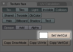
To set the vertex colour on a face, ensure it is active in UV Face Select mode and click on the small white square next to the button Set VertCol in the Texture Face tab.
This will pull up a colour palette from which you can select a new colour.
Clicking on Set VertCol next will apply that colour to all the vertices in that face.
You can now copy these settings onto other faces in your mesh with Copy DrawMode as usual.
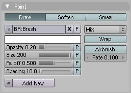
 Alternatively you can 'paint' vertex colours straight onto your mesh using the Vertex Paint mode, found in the dropdown menu at the base of any viewport.
This will present a new tab called Paint in the Editing panel.
It looks similar to the Paint tab presented when in Texture Paint mode:
Alternatively you can 'paint' vertex colours straight onto your mesh using the Vertex Paint mode, found in the dropdown menu at the base of any viewport.
This will present a new tab called Paint in the Editing panel.
It looks similar to the Paint tab presented when in Texture Paint mode:

Paint tab in Vertex Paint mode with a yellow colour selected. Note the mix buttons to the right will determine how your vertex colours should mix with existing colours on the mesh. Note: You can combine Vertex Colours and Textures in your work, one 'on top' of the other. For instance if you wanted one part of your textured mesh to have a yellow tinge, you could colour the vertices in that region. The texture data and vertex data will be mixed together based on the mixing mode you have chosen.
Packing the Image (or sound or video)
A common problem in the development of multimedia projects is keeping track of the many different files that a multimedia project inevitably depends on.
Blender provides a neat solution to this problem.
Each Blender file (ending in *.blend) can be thought of as an archive - a bit like a ZIP file.
When you add external data to your Blender project (a texture, a sound, a video) you have the option of 'packing' it into your Blender file so that you don't need to distribute that file separately.
You can then confidently distribute your Blender project knowing that when someone else opens up the file in somewhere else this data will not be missing in your scene.
At any point you can also 'unpack' these files, work on them and re-pack them.
Texturing Tutorial (basic)
Keywords: UV/Image Editor, Face Select mode, DrawMode, Cube projection
Let's take the chair we made in the previous lesson and texture it now, using some of what is written above.
First load up the chair in Blender and go into UV Face Select mode in a viewport (see Selecting Faces above).
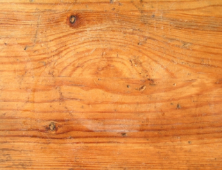
Save this wood texture to the same directory that the Blender file of the chair is saved (right-click ->save as in most browsers).
<mention texture formats!>
 We're currently using the Solid viewport shading type which draws no texture information and only provides a default lighting for your mesh.
To be sure we can see what we're doing in the course of texturing and lighting our mesh we need to change to the Textured shading mode.
Do this now by clicking on the Viewport Shading menu at the base of the viewport you're working in.
Place the 3D cursor (the red and white ring in the scene) just to the left of your chair and in a Top View, spacebar Add->Lamp-Lamp.
The lamp will be added right where you placed the 3D cursor.
At this stage your mesh will go white.
Why? Because we haven't setup the faces to receive light yet.
Setting faces up to receive light is relatively simple: select all the faces in your mesh (A-key) and click on the button labelled Light in the Texture Face tab in the Editing panel (F9-Key).
This will enable the current active face (the face with a coloured border) to receive light from lights in our scene.
Now we need to ensure all the remaining faces can receive light too: clicking on Copy DrawMode will copy the settings from this face to all the other faces in your mesh.
Select the lamp and move it around to get a balance of light you like.
At this stage you should have something that looks like this:
We're currently using the Solid viewport shading type which draws no texture information and only provides a default lighting for your mesh.
To be sure we can see what we're doing in the course of texturing and lighting our mesh we need to change to the Textured shading mode.
Do this now by clicking on the Viewport Shading menu at the base of the viewport you're working in.
Place the 3D cursor (the red and white ring in the scene) just to the left of your chair and in a Top View, spacebar Add->Lamp-Lamp.
The lamp will be added right where you placed the 3D cursor.
At this stage your mesh will go white.
Why? Because we haven't setup the faces to receive light yet.
Setting faces up to receive light is relatively simple: select all the faces in your mesh (A-key) and click on the button labelled Light in the Texture Face tab in the Editing panel (F9-Key).
This will enable the current active face (the face with a coloured border) to receive light from lights in our scene.
Now we need to ensure all the remaining faces can receive light too: clicking on Copy DrawMode will copy the settings from this face to all the other faces in your mesh.
Select the lamp and move it around to get a balance of light you like.
At this stage you should have something that looks like this:
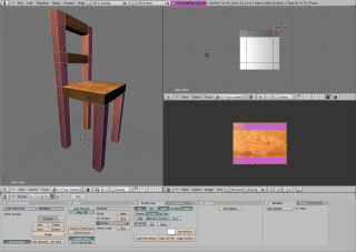
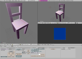 With all the faces still selected let's add some texture data to our faces.
Change one of your three viewports to the type UV/Image editor by clicking on the bottom left-most button in that viewport.
That button changes the current viewport type and looks like this:
With all the faces still selected let's add some texture data to our faces.
Change one of your three viewports to the type UV/Image editor by clicking on the bottom left-most button in that viewport.
That button changes the current viewport type and looks like this:
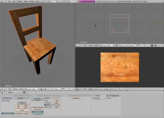
![]() Click on Image->Open in the UV/Image Editor menu and load in the wood texture you downloaded earlier.
This will immediately apply the texture to the faces.
Change to Object mode by changing the mode at the base of the viewport you're working with so we can see what we've made in all it's glory.
Here's what I have after doing all this:
Click on Image->Open in the UV/Image Editor menu and load in the wood texture you downloaded earlier.
This will immediately apply the texture to the faces.
Change to Object mode by changing the mode at the base of the viewport you're working with so we can see what we've made in all it's glory.
Here's what I have after doing all this:
 Looking closely at this textured mesh you'll notice that one texture has simply been applied to each face.
This is the default in Blender and while it works reasonably well for objects that have faces of equal proportion and textures with evenly repeating parts, it doesn't in others.
Taking this chair as an example, the parts of the chair looks like they're made up of several blocks of wood, not continuous pieces (look closely at the back legs and the seat).
Faces that are perpendicular to each other don't match up also, giving the impression that the parts of the chair aren't made of solid wood.
Let's play around with the placement of the texture on faces now to get an overall result that better describes the way the chair would be constructed with wood if it were real.
Enter UV Face Select mode again and select all the faces in all the legs, including the upper vertical parts that make the chair's back.
With your cursor still over that viewport, now hit Ukey, and LMB click on Cube.
The cubic projection will be represented in the UV/Image Editor as two strips of faces vertically aligned with the texture.
If you look at the chair now, you'll see that the wood grain goes left to right across the leg, eg not along the leg.
This is not the way a wooden chair would be made, so let's rotate the projection 90 degrees to make the grain implied in the texture go along the leg.
With your mouse cursor over the UV/Image Editor hit A-key to select all the vertices in the projection.
They should all go pink.
Now hit R-key (just as you would with an object or parts of a mesh) and - while holding the control key down - rotate the projection 90 degrees.
Once done hit ENTER or LMB and use S-key to scale the projection up so that it just fits within the limits of the texture itself.
Note: if we scaled the projection up to be larger that the texture, it would tile the texture, meaning it would visibly repeat across the selected faces.
This is what I have after doing this.
Looking closely at this textured mesh you'll notice that one texture has simply been applied to each face.
This is the default in Blender and while it works reasonably well for objects that have faces of equal proportion and textures with evenly repeating parts, it doesn't in others.
Taking this chair as an example, the parts of the chair looks like they're made up of several blocks of wood, not continuous pieces (look closely at the back legs and the seat).
Faces that are perpendicular to each other don't match up also, giving the impression that the parts of the chair aren't made of solid wood.
Let's play around with the placement of the texture on faces now to get an overall result that better describes the way the chair would be constructed with wood if it were real.
Enter UV Face Select mode again and select all the faces in all the legs, including the upper vertical parts that make the chair's back.
With your cursor still over that viewport, now hit Ukey, and LMB click on Cube.
The cubic projection will be represented in the UV/Image Editor as two strips of faces vertically aligned with the texture.
If you look at the chair now, you'll see that the wood grain goes left to right across the leg, eg not along the leg.
This is not the way a wooden chair would be made, so let's rotate the projection 90 degrees to make the grain implied in the texture go along the leg.
With your mouse cursor over the UV/Image Editor hit A-key to select all the vertices in the projection.
They should all go pink.
Now hit R-key (just as you would with an object or parts of a mesh) and - while holding the control key down - rotate the projection 90 degrees.
Once done hit ENTER or LMB and use S-key to scale the projection up so that it just fits within the limits of the texture itself.
Note: if we scaled the projection up to be larger that the texture, it would tile the texture, meaning it would visibly repeat across the selected faces.
This is what I have after doing this.
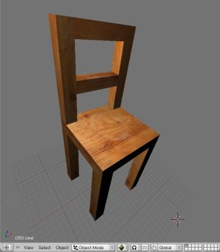
 Now hit A-key again and select the seat of your chair and apply a cube projection to that whole area and do the same for the two other pieces that cross the two back legs.
That should be enough to produce a reasonably convincing low-polygon, single-texture chair.
Here's the result I got:
Now hit A-key again and select the seat of your chair and apply a cube projection to that whole area and do the same for the two other pieces that cross the two back legs.
That should be enough to produce a reasonably convincing low-polygon, single-texture chair.
Here's the result I got:
 Next consider learning about Rendering.
Rendering Quickstart Guide
'Rendering' can be understood as the whole process of calculating how objects in a scene respond to virtua-l light and presenting the result.
This result will be drawn to an area of your computer screen or to a single image file - or both at the same time.
Rendered animations are long sequence of these images that are compressed using a particular codec (like Ogg Theora or DivX) and stored in a container file (like AVI or MOV).
Blender provides two different rendering engines to use when making stills or animations: YAFRAY and the standard Blender Internal renderer.
YAFRAY (humbly derived from "Yet Another Free Ray tracer") is much more advanced than the standard Blender renderer as it makes calculations based on the implied casting of virtual light as though they were real 'rays'.
This means it can calculate things such as the refraction of light through an object with a glass material, or the glow effect produced when light strikes a surface.
The Blender Internal renderer doesn't calculate the bouncing of lights of surfaces.
Instead it just calculates shadows as though the rays passed across the scene until they strike a surface at which point they are absorbed.
YAFRAY can also exploit multiple-CPU systems, like rendering clusters.
Rendering with YAFRAY is an advanced topic and is best used after acquiring a solid understanding of how materials work.
For this reason I won't cover it here.
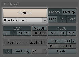
The Render Panel
The rendering panel contains most of what we need in order to setup and start our render.
Accessing this panel is done by clicking on the icon Scene (F10key) and then the button named Render Buttons.
Changing the render format
Just as the name suggests, the Format tab is where we change the dimensions and type of image to be rendered. There are a wide variety of image formats to choose from with Jpeg as the default.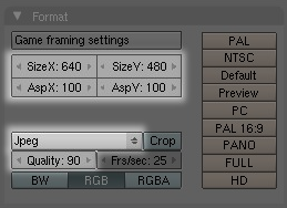
Placing a camera
You can only render with a camera in your scene as the rendered image is drawn from the camera view, not the viewport. SPACEBAR->Add-Camera will add a camera to your scene. It will always be added with the viewplane of the camera being parallel to the viewport itself. This can be quite handy. You can position a camera in a viewport that has a view angle you like and move it from there accordingly until you get the right position. NumPad-0 will take you to the view of the camera in any viewport.Working with lights.
Like materials, lights are intrinsic to the rendering process. A scene can be dense with elements but if it doesn't have a light, or surfaces that emit light, a black image will be all that's rendered. So far we've only worked with the default Lamp object, which really doesn't offer us much control over the casting of light in our scene. The Lamp Buttons panel provides you with a variety of options for manipulating the distribution, colour and type of light in your scene. To access this panel select your light and click on the Shading buttons icon (F10key) and then select the Lamp button, which has a lightbulb as an icon: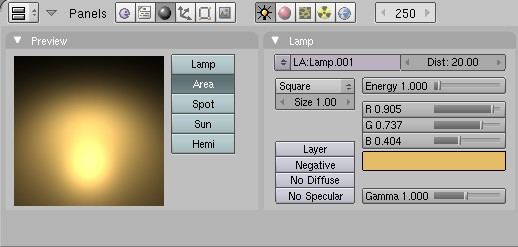 Just as in the corporeal world, combinations of lights with different colours can work very well to produce interesting shadows and create more visible dimensional detail on a surface.
Rendering and saving the image to disk
Once your scene is setup, you've chosen the dimensions and format of the image and you have a camera in your scene, save your work. Then press the Render button or F12key to start a render process. A small window will pop-up and you'll see the render take place, piece by piece. When it has finished you can save out this image to disk by going to the main Blender menu and File->Save Image (F3-key). This will pull up a file browser enabling you to save the image somewhere on your local hardisk.
The Blender Internal Renderer
First let's load and prepare a scene for some rendering.
Renderers in Blender pay special attention to materials; despite the fact that we can see the UV texture on our chair the renderer won't consider it when it makes its calculations.
Our example (I'm using a chair) would just be rendered gray as though in the Shaded viewport drawing mode..
Note: the Blender Game Engine doesn't need materials on objects to render them in real time.
Perhaps a little confusingly, materials are found in the Shading (F5key) panel.Click on the Shading button and then on the Materials button.
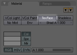 The materials panel is very powerful: we could create a much more complex material here for rendering.
For instance we could make the surface reflective, make it translucent or even appear 'bumpy' using other surface effects.
We'll cover this later in another section.
Now that we have a very simple material we can move on to setting up our render camera.
In a Perspective View (F5-key toggles this) try to get a view angle you like and when ready add a camera with SPACEBAR->Add->Camera.
Now click on the menu of that viewport and View->Align view->Align Active Camera to View.
This will take the current camera and snap it to the implied position and orientation of that viewport.
The materials panel is very powerful: we could create a much more complex material here for rendering.
For instance we could make the surface reflective, make it translucent or even appear 'bumpy' using other surface effects.
We'll cover this later in another section.
Now that we have a very simple material we can move on to setting up our render camera.
In a Perspective View (F5-key toggles this) try to get a view angle you like and when ready add a camera with SPACEBAR->Add->Camera.
Now click on the menu of that viewport and View->Align view->Align Active Camera to View.
This will take the current camera and snap it to the implied position and orientation of that viewport.
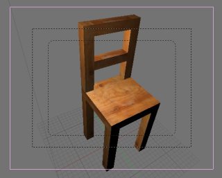 Right now we're looking through the view of that camera.
The pink square around my chair is the camera object itself, which seen from another view looks like a pyramidal form.
The outer-most black dotted lines show us the limits of the rendering area itself: anything outside these dotted lines won't be rendered.
So we need to make sure our chair is right inside this area before we render.
The technique for doing this usually involves using the other views (Top and Side are good) to move the camera around until what you see in the Perspective view looks about right.
Here's what I have after a bit of playing around:
Right now we're looking through the view of that camera.
The pink square around my chair is the camera object itself, which seen from another view looks like a pyramidal form.
The outer-most black dotted lines show us the limits of the rendering area itself: anything outside these dotted lines won't be rendered.
So we need to make sure our chair is right inside this area before we render.
The technique for doing this usually involves using the other views (Top and Side are good) to move the camera around until what you see in the Perspective view looks about right.
Here's what I have after a bit of playing around:
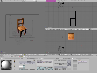 Now go to the Rendering buttons, set the render format and size (see Changing the Render Format above) and hit F12-key or click the button labelled Render.
Here's what I got:
Now go to the Rendering buttons, set the render format and size (see Changing the Render Format above) and hit F12-key or click the button labelled Render.
Here's what I got:
This certainly isn't all that exciting.
It's just a raw render of the chair against a default background.
No shadows are cast because there's nothing to cast those shadows on.
Let's make this better.
Make a cube around your chair about the size of a room and in UV Face Select mode, in the Texture Face tab, make the faces of this room two-sided and enable them for light and also shadow.
If you can't remember how to do this, see the section Texturing.
Make sure that the floor of this room is right under the feet of your chair.
Now let's play around with the lighting a little.
The default Blender lamp doesn't provide us with any way of directing the light: the rays themselves cannot be oriented.
Light in the real world however never operates like this, let alone indoors from artificial lights.
Blender provides several different types of lights that give us more to play with in this regard.
Select your lamp and the Shading buttons (F10-key) and then click on the small icon that represents a light.
Change that light to the type Spot and the light will suddenly change into a cone form.
This represents the projection of the light in the scene.
By rotating the Spot, repositioning it, changing the energy (strength of the light) and colour of the light you can get some good results easily.
Here's my scene before rendering, with two spots - one of which has much less energy than the other and is coloured yellow.
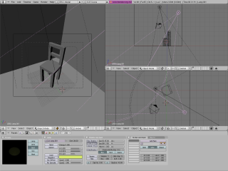 Rendering this scene produced the following image: